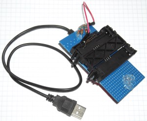
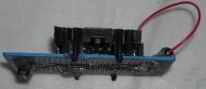
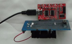
Tired of playing with wires, breadboard and so on to interface synchronous smart cards with bus pirate, I made a kind of shield. Thank you Arduino for teaching me this way of thinking 🙂
Bill of materials
- 1x breadboard solder
- 1x smart card socket (e.g. this one, this one, or ebay : here and here)
- 1x female header [2X5]
- 3x pull-up resistors [2kΩ-10kΩ] from C1, C3 and C7 to VCC 5V (I added a piece of wire to connect them, or not)
- Wire
Tools
- Soldering station/iron
- Glue gun
Connections pinout
Card is connected to Bus Pirate as follow (5 wires) (see connector pinout on wikipedia page):

SLE4442 <—> Bus Pirate
C1=VCC <—> +5V
C2=RST <—> +AUX (and pull-up resistor to +5V)
C3=CLK <—> CLK (and pull-up resistor to +5V)
C4 is not connected
C5=GND <—> GND
C6] is not connected
C7=I/O <—> MOSI (and pull-up resistor to +5V)
C8 is not connected


Pingback: SLE4442 Bus Pirate GUI | Yaehob – Yet Another E-Hobbyist blog…
Hi, you are my savior. I was desperately looking the net for a schema to build one of theses reader.
Using the bus pirate is genius move.
Can you leave a more specific (Fritzing?) schema of the wirings ?
LikeLike
Hi!
Thank you, you’re welcome!
I’m not (yet) used to Fritzing, anyway I’ve just had a look but it seems there is no smart card connector (there are readers but not simple smart card). Anyway, I’ve just edited the post. I hope it’s clearer now 🙂 Let me know if you need more…
LikeLike
Hi, thanks for the editing the post, it is more precise.
But, what I was looking, is the wirering you made with the pull-up resistors.
And I am wondering how the red wire works ?
I have got the same plastic reader; but with a TERIDIAN(73S8009R-IL) chip wired to the output, and 13 pin going out. I do not find any info about it.
May be I can upload a picture of it…
M.
LikeLike
Yeah I would also like the connections schema. I want to build cheap smart card reader/writer for my projects.
LikeLike
Connections are described as this:
SLE4442 Bus Pirate
C1=VCC +5V
C2=RST +AUX (and pull-up resistor to +5V)
C3=CLK CLK (and pull-up resistor to +5V)
C4 is not connected
C5=GND GND
C6 is not connected
C7=I/O MOSI (and pull-up resistor to +5V)
C8 is not connected
LikeLike
What does it mean and pull up resistors? Which type of connection is there parallel?
So the connection is as you described for the pinout on the reader and bus pirate I understand this part. But how exacly red wire is connected with the pull up resistors?
Is it the 5V output from bus pirate connected to pull up resistors and then to the pins on reader?
I am still experimenting with electronic stuff, i need some help
LikeLike
Yes, you’re right!
LikeLike
OK. I failed. Can you please sell this shield to me?
LikeLike
Just some notes.
Actually it doesn’t need all those pull up resistors, though.
Even if into the pics in the project it shown a Bus Pirate v3b, you have to consider that Bus Pirate v2go/v3/later already have its own pull up resistors on MOSI, CLOCK, MISO and CS wires.
No matter which one is used, the only noteworthy thing to which to pay attention is the value of the pull up resistor on MOSI wire because early versions of the Bus Pirate use a 10kohm while latest ones a 2kohm in order to drive correctly 1-Wire protocol devices.
Anyway, regardless of the actual pull-up resistor values (10kohm or 2kohm) used into the version of the Bus Pirate used for the project, there on the circuit board already are the pull up resistors, so the new ones on the smart card shield will end up in parallel to those already present, obtaining resistance values lower than the lowest value of the constituent parallel, that could be a problem.
Problem or not, it is best to avoid parallel for the pull up resistors hence it should be better add on the smart card shield only the pull up resistor for the AUX signal and use the ones already there on the Bus Pirate for the other wires even because the software designed to deal with the shield surely use the pull up features of the Bus Pirate.
So in the end actually you need only one [2kΩ-10kΩ] as pull up resistor for the C2=RST +AUX wire.
A wise thing into the project is the possibility to provide or not +5V on it in order to activate/deactivate it.
Very easy to assemble even for newbies, cheap but great “for dummies style” hardware project for everyone who has a Bus Pirate.
The related software is very good and works like a charm, a must.
Very useful job, well done!
LikeLike
…”Even if into the pics in the project it shown a Bus Pirate v3b, you have to consider that Bus Pirate v2go/v3/later already >>has<<< its own pull up resistors on MOSI, CLOCK, MISO and CS wires."…
Sorry by that…
LikeLike
http://dangerousprototypes.com/docs/Bus_Pirate_v4_vs_v3_comparison
according to this only hardware v4 which is still experimental has pull up resistors build in
LikeLike
Hello “A”,
that’s not correct, please look at the schematic diagrams of BusPirate revision 3 and 4.
About pull-up resistors the only difference between revision 3 and 4 is that in the latest the power supply for them is wired inside while in the previous hardware revision 3 it’s need to them with the desired power supply level (+5V/+3,3V/GND).
In the end Bus Pirate revision 4 doesn’t require a cable for the power supply of the pull-up resistors while instead the revision 3 requires it, but the resistors are already present in both hardware revisions, there is no need to add them.
The fact is that since the pull-up resistors are already provided by the Bus Pirate as hardware on MOSI, CLOCK, MISO and CS it’s no need to add them on the shield but only add a new one resistor for the AUX wire which instead by default is not provided for pull-up on the Bus Pirate Revision 3.
That is.
LikeLike
http://dangerousprototypes.com/blog/2014/10/17/bus-pirate-smart-card-shield/
LikeLike
Hello “A”,
that’s not correct, please look at the schematic diagrams of BusPirate revision 3 and 4.
About pull-up resistors the only difference between revision 3 and 4 is that in the latest the power supply for them is wired inside while in the previous hardware revision 3 it’s need to them with the desired power supply level (+5V/+3,3V/GND).
In the end Bus Pirate revision 4 doesn’t require a cable for the power supply of the pull-up resistors while instead the revision 3 requires it, but the resistors are already present in both hardware revisions, there is no need to add them.
The fact is that since the pull-up resistors are already provided by the Bus Pirate as hardware on MOSI, CLOCK, MISO and CS it’s no need to add them on the shield but only add a new one resistor for the AUX wire which instead by default is not provided for pull-up on the Bus Pirate Revision 3.
That is.
LikeLike
Hello i also found this oroject great. I use a bus pirate v.6 and rhe other Stuffs. I do as described but by testing imly port COM4 seems to make something:
***BEGIN init SerialPort()****
***BEGIN close Serialport()****
***END close Serialport()****
***BEGIN init SerialPort()****
***END init SerialPort()***
***BEGIN init BusPirate()****
–>m
And nothing else. Would you know where is that problem?
I’am civil Eng. not so mutch idea from elektronik…;)
LikeLike